PE File Structure for Malware Analysis: A Practical Guide
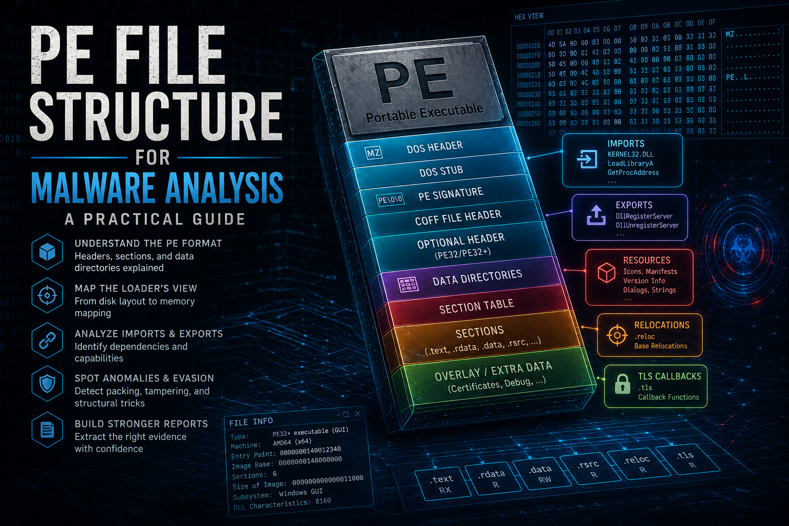
- Category: Malware Analysis
- Topics: Portable Executable, PE Format, Windows Internals, Reverse Engineering, Static Analysis, Digital Forensics, x86, x64, AIDebug
- Source article: Medium publication
- Published: 2026-08-10
- Preserved media: 34 image(s), including the cover, PE reference diagrams, AIDebug screenshots, and the Windows loader infographic.
- Published scope: Chapters 0–20 and references, matching the public Medium edition rather than the longer working draft.
Ecosystem Fit
This guide connects the Malware Analysis knowledge base, visual guides library, TrainSec helping materials, and hands-on lab collection. After mapping the image, use Strings Analysis for Malware Analysis to prioritize readable evidence and continue into Assembly for Malware Analysis to validate cross-references. Use the safe malware-analysis lab guide before inspecting unknown samples.
This independent article may be used as supplementary material for TrainSec's Malware Analyst Professional – Level 1. It is not part of the official course. See my complete course review.
The AIDebug 3.1 full release review shows how this PE workspace connects to file identification, function triage, String Intelligence, Ghidra reconstruction, and exportable evidence.
The Portable Executable format is the structural language of native Windows software. Executables, DLLs, drivers, control-panel applets, and many .NET assemblies all use the same broad container. Before Windows can start the code, its loader must answer a series of questions encoded in that container:
- What architecture is this image built for?
- Where should it be mapped?
- Which bytes contain code, initialized data, or zero-filled storage?
- Which DLLs and functions must be resolved?
- Where does execution begin?
- Which addresses require relocation?
- Does initialization code run before the nominal entry point?
- Which security mitigations and trust metadata are present?
A malware analyst asks the same questions—but with an adversarial assumption: every field is untrusted, names may be deceptive, timestamps may be forged, and different parsers may disagree.
This guide explains PE structure from that defensive perspective. It focuses on PE32 and PE32+ image files used by 32-bit and 64-bit Windows. It does not attempt to document every COFF object-file feature or every processor-specific relocation. Instead, it teaches the structures, calculations, and evidence that matter most during static analysis and reverse engineering.
For the next layer down, use Assembly for Malware Analysis. For the environment in which to inspect unknown files safely, begin with How to Build a Safe Malware Analysis Lab.
Scope and safety: Parsing is safer than executing, but parsers also contain vulnerabilities. Inspect untrusted PE files in an isolated analysis VM, keep tools patched, disable preview handlers and shell extensions, and never double-click a sample. All commands in this guide read metadata; none intentionally executes the target.
0. Using AIDebug for PE analysis
AIDebug provides a read-only PE structure workspace alongside hexadecimal inspection, disassembly, optional Ghidra reconstruction, and hash-indexed analysis history.
Install it inside the isolated analysis VM:
git clone https://github.com/anpa1200/AIDebug.git
cd AIDebug
python3 -m venv .venv
source .venv/bin/activate
python -m pip install -e .
Open a PE without executing it or transmitting evidence to a remote AI provider:
aidebug --binary /path/to/suspicious.exe --offline
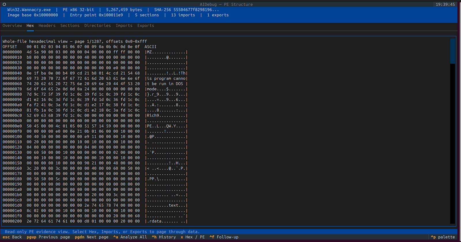
Press X in the main interface. AIDebug recognizes the PE and presents:
- complete file hex with offsets and ASCII;
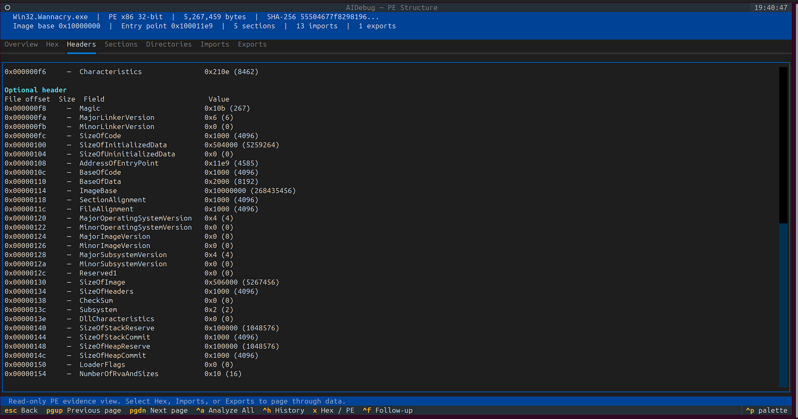
- DOS, NT, COFF, and optional headers;
- sections with RVA, VA, raw ranges, entropy, and characteristics;
- data-directory addresses and sizes;
- normal and delay-loaded imports;
- exports, ordinals, and forwarders;
- image base, entry point, SHA-256, and overlay boundaries.
Use PageUp and PageDown to navigate paged evidence, Home and End to
jump to its boundaries, and Escape to return to function analysis. P is an
additional shortcut for the PE workspace.
For C-like Ghidra reconstruction, restart with:
aidebug --binary /path/to/suspicious.exe --offline --decompile
The reconstruction is not original source. Verify its inferred types, addresses, imports, and control flow against the PE map and real instructions. AIDebug is a first-pass analysis environment, not the sole authority for every resource, relocation, TLS, certificate, load-configuration, exception, or CLR record; corroborate important findings with another parser.
Table of contents
- Using AIDebug for PE analysis
- Why PE structure matters
- The two views: file on disk and image in memory
- The address vocabulary: file offsets, RVAs, and VAs
- The high-level PE layout
- The DOS header, DOS stub, and PE signature
- The COFF file header
- The optional header: the loader's map
- Data directories: routes to important structures
- The section table and section data
- Imports, thunks, and the IAT
- Exports and forwarded functions
- Resources
- Base relocations and ASLR
- TLS data and callbacks
- Exception and unwind information
- Load configuration and exploit mitigations
- Authenticode certificates and signatures
- Debug data, the Rich header, and overlays
- .NET assemblies inside PE files
- How the Windows loader uses the image
- References
1. Why PE structure matters
PE metadata gives an analyst a fast, execution-free first model of a sample. It can reveal:
- architecture, subsystem, and image type;
- preferred base address and entry-point RVA;
- code and data regions with their intended memory permissions;
- imported modules and functions;
- exported entry points;
- embedded icons, manifests, version records, dialogs, strings, and binary resources;
- relocation, TLS, exception, and load-configuration data;
- digital signatures and debug artifacts;
- indicators of managed .NET code;
- inconsistencies associated with packing, corruption, or deliberate parser evasion.
The word can matters. A header describes how the image wants to be treated; it does not prove what executes. Imports suggest possible capabilities, section names suggest intended roles, and a signature reports a trust relationship. Runtime behavior still depends on code paths, arguments, environment, loader decisions, and data that may be decoded only after startup.
A strong PE analysis therefore has three layers:
- Structural observation: what the file declares and where the relevant bytes are.
- Behavioral inference: what those structures and referenced APIs suggest.
- Validation: what disassembly, decompilation, or controlled runtime evidence confirms.
The 1200km Malware Analysis knowledge base uses the same evidence-first discipline.
2. The two views: file on disk and image in memory
The most important PE concept is that a file's disk layout is not identical to its loaded memory layout.
On disk, the file is arranged for storage:
headers
section 1 raw bytes
section 2 raw bytes
section 3 raw bytes
optional certificate data
optional overlay
In memory, the loader creates an image organized by relative virtual addresses:
image base + headers
image base + section 1 RVA
image base + section 2 RVA
image base + section 3 RVA
zero-filled virtual tails
Two alignment rules drive the difference:
- FileAlignment aligns section data in the file.
- SectionAlignment aligns sections in virtual memory.
A typical PE might use a file alignment of 0x200 bytes and a section alignment of 0x1000 bytes. Consequently, bytes found at file offset 0x600 might be mapped at RVA 0x2000. Copying a file offset directly into a debugger address will often land in the wrong place.
What is not necessarily mapped
Not every byte in a PE file becomes part of the image:
- the certificate table is addressed by file offset and is not mapped as an ordinary image directory;
- arbitrary overlay data after the mapped section content is normally not mapped;
- debug information may be stored outside mapped sections;
- file-alignment padding and some section slack may have no meaningful loaded representation.
Conversely, memory can contain bytes that do not exist in the file. If a section's virtual size exceeds its raw size, the remaining memory is zero-filled.
This distinction explains why a disk scanner, a PE parser, a debugger, and a process-memory dumper can report different offsets and sizes without any of them necessarily being wrong.
3. The address vocabulary: file offsets, RVAs, and VAs
PE analysis becomes much easier when three address forms are kept separate.
| Term | Meaning | Example |
|---|---|---|
| File offset | Position from the first byte of the file | 0x640 |
| RVA | Relative virtual address from the image base | 0x1234 |
| VA | Virtual address in a loaded process | 0x0000000140001234 |

The basic relationship is:
VA = actual image base + RVA
If the image is loaded at its preferred base:
VA = OptionalHeader.ImageBase + RVA
ASLR may choose a different actual base, so an address copied from one process run may not be valid in the next.
Converting an RVA to a file offset
For an RVA inside a section:
delta       = RVA - section.VirtualAddress
file offset = section.PointerToRawData + delta
The calculation is valid only when the delta points to bytes actually present in the section's raw file data. If delta >= SizeOfRawData but the RVA is still inside the section's virtual range, the address refers to zero-filled memory rather than a byte stored in the file.
For an RVA inside the headers, the RVA often equals the file offset, subject to a valid SizeOfHeaders and file bounds.
Analyst rule: Never convert an RVA with one global subtraction. Select the containing section first, then apply that section's mapping.
4. The high-level PE layout
A normal PE image follows this broad order:
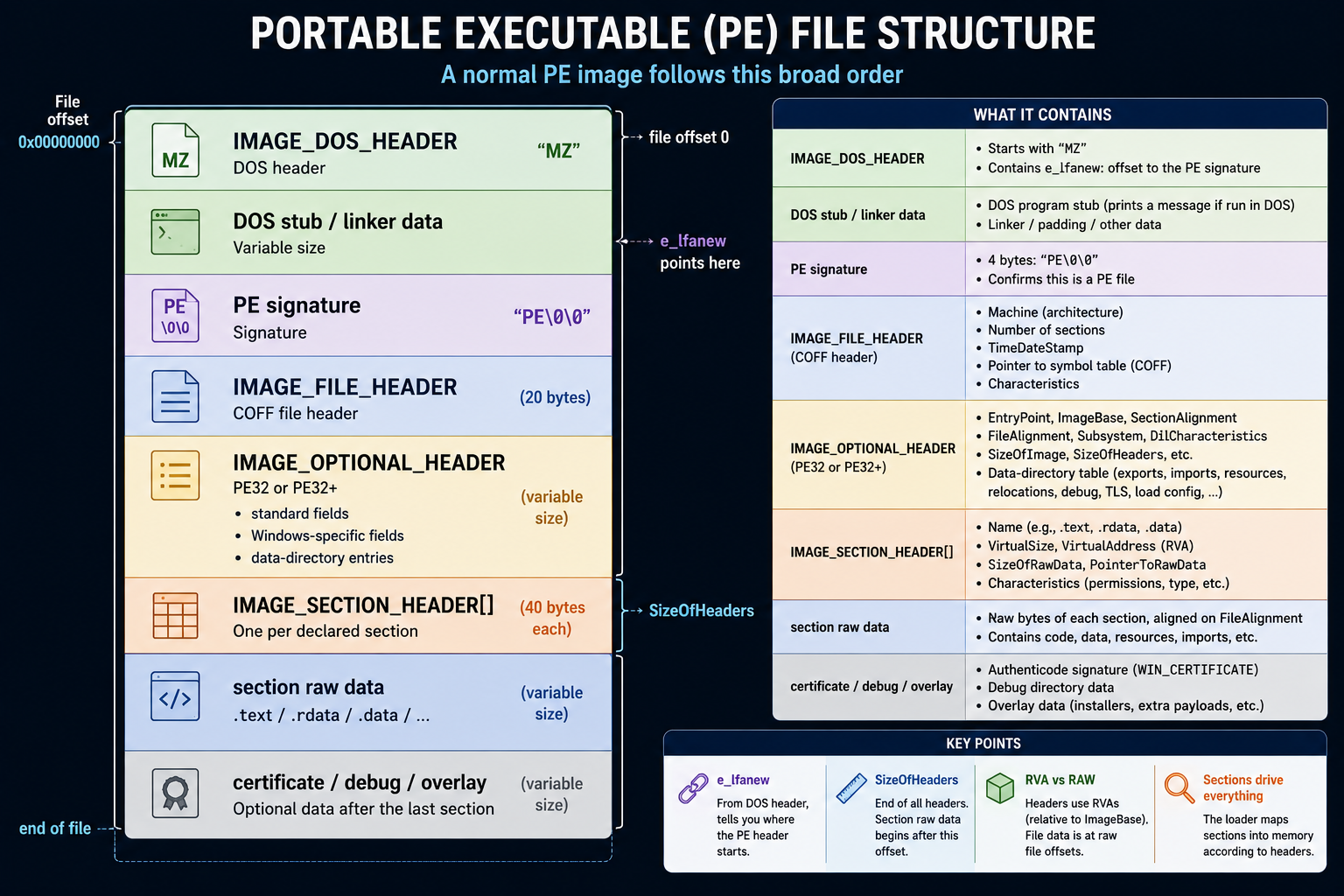
+-------------------------------+  file offset 0
| IMAGE_DOS_HEADER              |  "MZ"
+-------------------------------+
| DOS stub / linker data        |
+-------------------------------+  e_lfanew points here
| PE signature                  |  "PE\0\0"
+-------------------------------+
| IMAGE_FILE_HEADER             |  COFF file header
+-------------------------------+
| IMAGE_OPTIONAL_HEADER         |  PE32 or PE32+
|   standard fields             |
|   Windows-specific fields     |
|   data-directory entries      |
+-------------------------------+
| IMAGE_SECTION_HEADER[]        |  one per declared section
+-------------------------------+  SizeOfHeaders
| section raw data              |
| .text / .rdata / .data / ... |
+-------------------------------+
| certificate / debug / overlay |
+-------------------------------+  end of file
The format is navigated through offsets and counts, not by assuming that every compiler emits an identical layout.
Important consequences:
- the PE header does not have to begin at a fixed offset;
- the optional header has a size recorded in the file header;
- the number of data directories must be read before indexing one;
- the section table location depends on the optional-header size;
- section names are labels, not authoritative types;
- directory structures can live in sections with unexpected names.
5. The DOS header, DOS stub, and PE signature
IMAGE_DOS_HEADER
The first two bytes of a conventional PE image are:
4D 5A MZ
This is the e_magic field of IMAGE_DOS_HEADER. The legacy header exists because PE evolved from DOS-compatible executable conventions.
The field that matters most to a modern analyst is e_lfanew at file offset 0x3c. It contains the file offset of the PE signature.
Conceptually:
pe_offset = dos_header.e_lfanew;
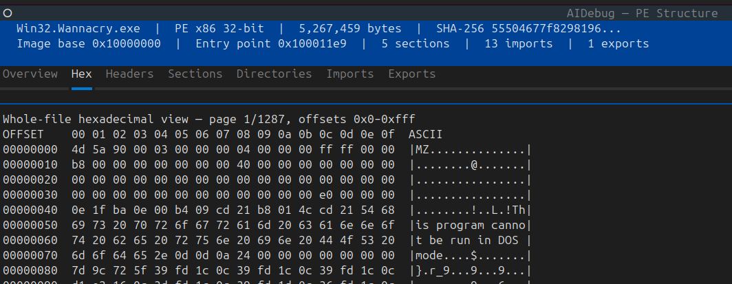
Before following it, a parser must validate that:
- the file is large enough to contain
e_lfanew; - the value does not point before required DOS-header data;
- the target offset and subsequent headers fit inside the file;
- arithmetic used to calculate later structures does not overflow.
The MZ magic alone does not prove that the file contains a valid PE image.
DOS stub
The region between the DOS header and the PE signature often contains a small DOS-mode program that prints:
This program cannot be run in DOS mode.

Modern linkers may also place toolchain-specific data in this area. Malware can overwrite, expand, encrypt, or repurpose it. Treat unusual stub content as evidence to investigate, not an automatic verdict.
PE signature
At the offset given by e_lfanew, an image normally contains:
50 45 00 00 PE\0\0
The 4-byte signature is followed immediately by the 20-byte COFF file header.
6. The COFF file header
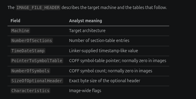
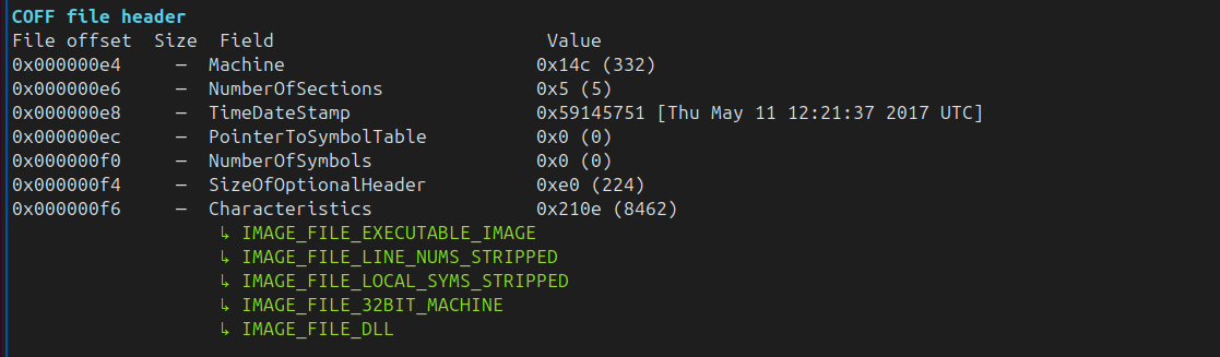
The IMAGE_FILE_HEADER describes the target machine and the tables that follow.
| Field | Analyst meaning |
|---|---|
Machine | Target architecture |
NumberOfSections | Number of section-table entries |
TimeDateStamp | Linker-supplied timestamp-like value |
PointerToSymbolTable | COFF symbol-table pointer; normally zero in images |
NumberOfSymbols | COFF symbol count; normally zero in images |
SizeOfOptionalHeader | Exact byte size of the optional header |
Characteristics | Image-wide flags |
Machine types
Common values include:
| Value | Constant | Meaning |
|---|---|---|
0x014c | IMAGE_FILE_MACHINE_I386 | Intel 386-compatible 32-bit x86 |
0x8664 | IMAGE_FILE_MACHINE_AMD64 | x86-64 |
0x01c4 | IMAGE_FILE_MACHINE_ARMNT | ARM Thumb-2 |
0xaa64 | IMAGE_FILE_MACHINE_ARM64 | ARM64 |
Do not infer architecture from the filename or MZ signature. Use Machine together with the optional-header magic.
Number of sections
NumberOfSections tells a parser how many 40-byte section headers follow the optional header. Validate the resulting table against the file size:
section table offset
  = e_lfanew
  + 4                         # PE signature
  + 20                        # IMAGE_FILE_HEADER
  + SizeOfOptionalHeader
Then confirm:
section table offset + NumberOfSections × 40 <= file size
An absurd section count can be corruption, parser fuzzing, or deliberate evasion.
TimeDateStamp
Historically, TimeDateStamp was interpreted as seconds since 1 January 1970 UTC. In real investigations it may be:
- a plausible linker time;
- zero;
- copied from another sample;
- intentionally backdated or future-dated;
- transformed for a reproducible build;
- modified by a packer or post-processing tool.
Record it as a claimed or tool-generated value—not as proof of compilation time or attribution.
Characteristics
Useful flags include:
IMAGE_FILE_EXECUTABLE_IMAGE;IMAGE_FILE_DLL;IMAGE_FILE_SYSTEM;IMAGE_FILE_LARGE_ADDRESS_AWARE;IMAGE_FILE_RELOCS_STRIPPED;IMAGE_FILE_32BIT_MACHINE.
These bits should be interpreted with Machine, the optional header, and the actual directory content. Contradictions are worth documenting.
7. The optional header: the loader's map
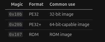
The optional header is optional for COFF object files but required for executable images. Its first field, Magic, selects the layout:
| Magic | Format | Common use |
|---|---|---|
0x10b | PE32 | 32-bit image |
0x20b | PE32+ | 64-bit-capable image |
0x107 | ROM | ROM image |
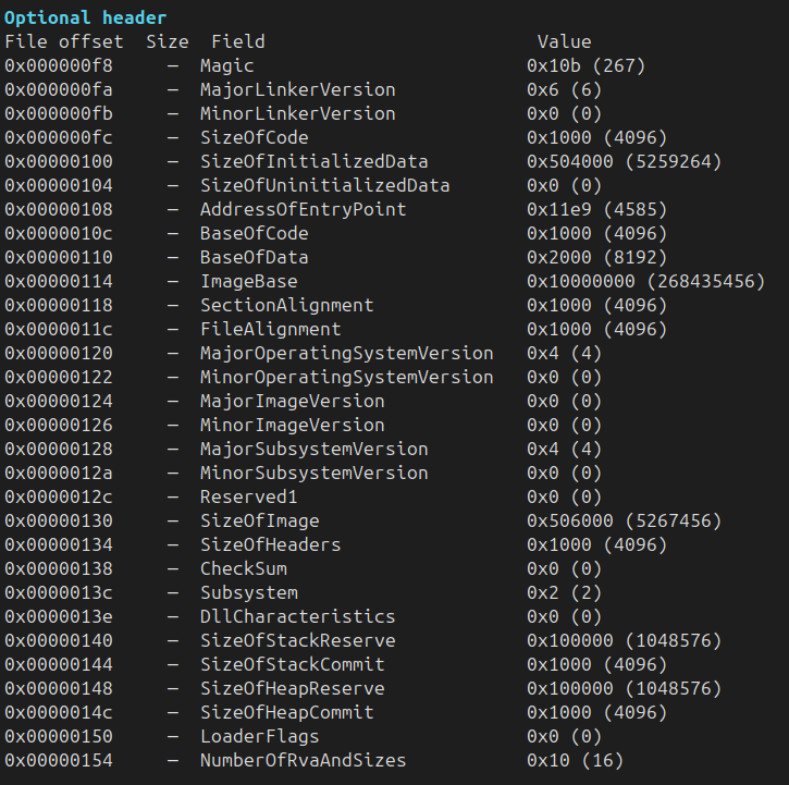
PE32+ is not simply PE32 with every field widened. Notable differences include:
ImageBaseis 8 bytes in PE32+;- stack and heap reserve/commit fields are 8 bytes in PE32+;
BaseOfDataexists in PE32 but is absent in PE32+;- import thunk entries are 32 bits in PE32 and 64 bits in PE32+.
Always parse according to Magic and respect SizeOfOptionalHeader.
Standard fields
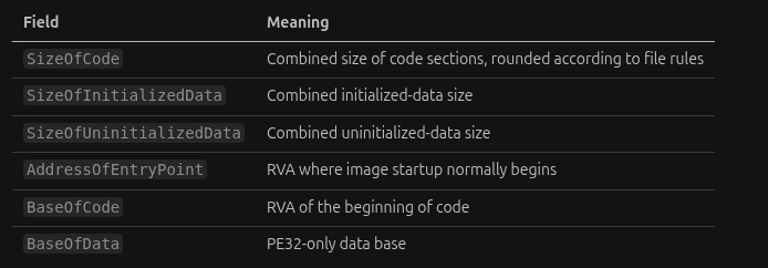
High-value standard fields include:
| Field | Meaning |
|---|---|
SizeOfCode | Combined size of code sections, rounded according to file rules |
SizeOfInitializedData | Combined initialized-data size |
SizeOfUninitializedData | Combined uninitialized-data size |
AddressOfEntryPoint | RVA where image startup normally begins |
BaseOfCode | RVA of the beginning of code |
BaseOfData | PE32-only data base |
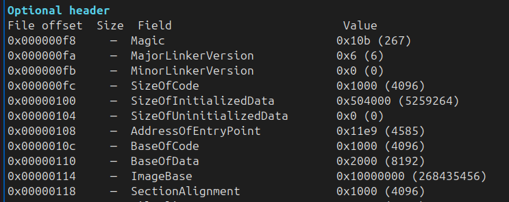
AddressOfEntryPoint is not necessarily a source-level main or WinMain. It commonly points to:
- C/C++ runtime startup;
- a DLL initialization stub;
- a driver entry routine;
- a packer or protector stub;
- a managed-runtime bootstrap;
- a custom loader.
TLS callbacks can execute before the nominal entry point. A zero entry-point RVA is valid for an image that has no entry point.
Windows-specific fields
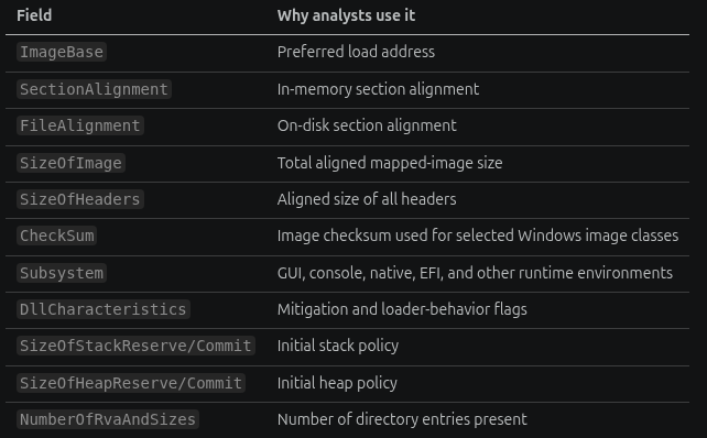
| Field | Why analysts use it |
|---|---|
ImageBase | Preferred load address |
SectionAlignment | In-memory section alignment |
FileAlignment | On-disk section alignment |
SizeOfImage | Total aligned mapped-image size |
SizeOfHeaders | Aligned size of all headers |
CheckSum | Image checksum used for selected Windows image classes |
Subsystem | GUI, console, native, EFI, and other runtime environments |
DllCharacteristics | Mitigation and loader-behavior flags |
SizeOfStackReserve/Commit | Initial stack policy |
SizeOfHeapReserve/Commit | Initial heap policy |
NumberOfRvaAndSizes | Number of directory entries present |
Alignment
The specification normally requires:
SectionAlignment >= FileAlignment
FileAlignment is generally a power of two between 512 bytes and 64 KiB. If SectionAlignment is below the architecture's page size, FileAlignment must match it, and low-alignment images follow tighter mapping rules.
Values that are zero, non-power-of-two where prohibited, contradictory, or inconsistent with section locations are structural warnings.
SizeOfImage and SizeOfHeaders
SizeOfImage covers the loaded headers and sections rounded to SectionAlignment. It is a memory-image size, not the file length.
SizeOfHeaders covers the DOS area, PE signature, file header, optional header, and section table rounded to FileAlignment.
A file can be larger than SizeOfImage because disk-only data may follow mapped sections. It can also be smaller than SizeOfImage because uninitialized and zero-filled virtual space does not require raw bytes.
Subsystem
Common values describe:
- Windows GUI;
- Windows console;
- native subsystem;
- EFI application or driver;
- boot application.
Subsystem affects startup expectations but does not identify intent. A console binary can hide its window; a GUI binary can allocate a console; a native image may be a legitimate system component or a specialized malicious implant.
DllCharacteristics and mitigation clues
High-value flags include:
IMAGE_DLLCHARACTERISTICS_DYNAMIC_BASE— image can participate in base relocation/ASLR;IMAGE_DLLCHARACTERISTICS_HIGH_ENTROPY_VA— supports high-entropy 64-bit address space where applicable;IMAGE_DLLCHARACTERISTICS_NX_COMPAT— image is compatible with data-execution prevention;IMAGE_DLLCHARACTERISTICS_GUARD_CF— image was built with Control Flow Guard instrumentation/metadata;IMAGE_DLLCHARACTERISTICS_NO_SEH— image does not use structured exception handling under applicable conditions;IMAGE_DLLCHARACTERISTICS_TERMINAL_SERVER_AWARE.
A flag is a declaration. Confirm that supporting structures exist—for example, relocations for practical ASLR and load-configuration data for CFG.

8. Data directories: routes to important structures
The end of the optional header contains an array of address-and-size pairs. These are data directories.
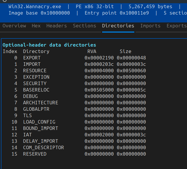
Before reading directory index n, validate:
NumberOfRvaAndSizes > n;SizeOfOptionalHeaderis large enough to contain that entry;- the address and size are internally consistent;
- the referenced range maps to valid file bytes when disk content is required.
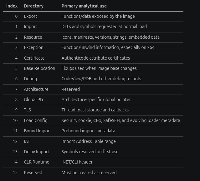
The commonly defined directory indexes are:
| Index | Directory | Primary analytical use |
|---|---|---|
| 0 | Export | Functions/data exposed by the image |
| 1 | Import | DLLs and symbols requested at normal load |
| 2 | Resource | Icons, manifests, versions, strings, embedded data |
| 3 | Exception | Function/unwind information, especially on x64 |
| 4 | Certificate | Authenticode attribute certificates |
| 5 | Base Relocation | Fixups used when image base changes |
| 6 | Debug | CodeView/PDB and other debug records |
| 7 | Architecture | Reserved |
| 8 | Global Ptr | Architecture-specific global pointer |
| 9 | TLS | Thread-local storage and callbacks |
| 10 | Load Config | Security cookie, CFG, SafeSEH, and evolving loader metadata |
| 11 | Bound Import | Prebound import metadata |
| 12 | IAT | Import Address Table range |
| 13 | Delay Import | Symbols resolved on first use |
| 14 | CLR Runtime | .NET/CLI header |
| 15 | Reserved | Must be treated as reserved |
The certificate-table exception
For almost every image directory, the first value is an RVA. Directory index 4 is the major exception: its “virtual address” field is a file offset to the certificate table because certificate data is not loaded as part of the image.
This exception breaks generic “directory RVA to section” code and is a frequent source of parser mistakes.
A zero directory
An address and size of zero usually mean the directory is absent. An address with zero size, a size with zero address, a range outside the image, or a range that crosses unrelated data should be treated cautiously.
The directory does not need to live in the section whose conventional name suggests it. Imports may be found in .rdata, .idata, or a custom section. Parse by directory address, not by name.
9. The section table and section data
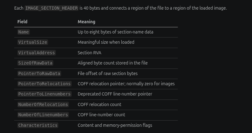
Each IMAGE_SECTION_HEADER is 40 bytes and connects a region of the file to a region of the loaded image.
| Field | Meaning |
|---|---|
Name | Up to eight bytes of section-name data |
VirtualSize | Meaningful size when loaded |
VirtualAddress | Section RVA |
SizeOfRawData | Aligned byte count stored in the file |
PointerToRawData | File offset of raw section bytes |
PointerToRelocations | COFF relocation pointer; normally zero for images |
PointerToLinenumbers | Deprecated COFF line-number pointer |
NumberOfRelocations | COFF relocation count |
NumberOfLinenumbers | COFF line-number count |
Characteristics | Content and memory-permission flags |
Common section names
| Name | Conventional content |
|---|---|
.text | Executable code |
.rdata | Read-only data, imports, strings, metadata |
.data | Initialized writable data |
.bss | Uninitialized writable data |
.idata | Import structures |
.edata | Export structures |
.rsrc | Resources |
.reloc | Base relocations |
.pdata | Exception/function table |
.tls | TLS template/callback-related data |
.debug | Debug information |
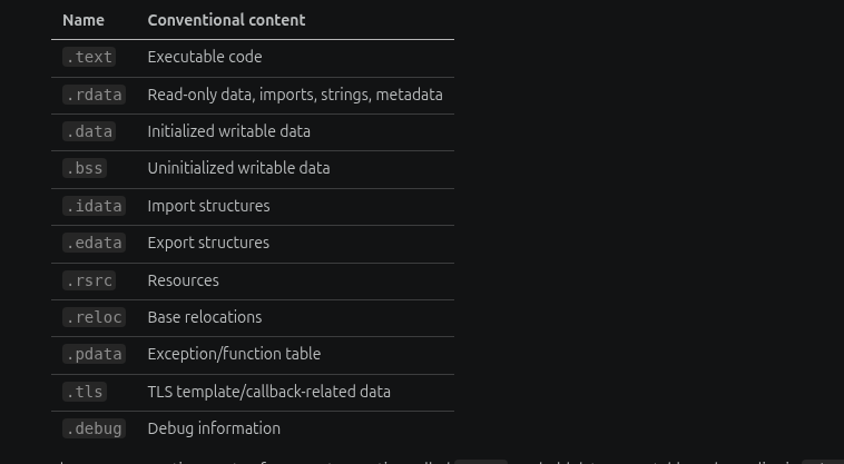
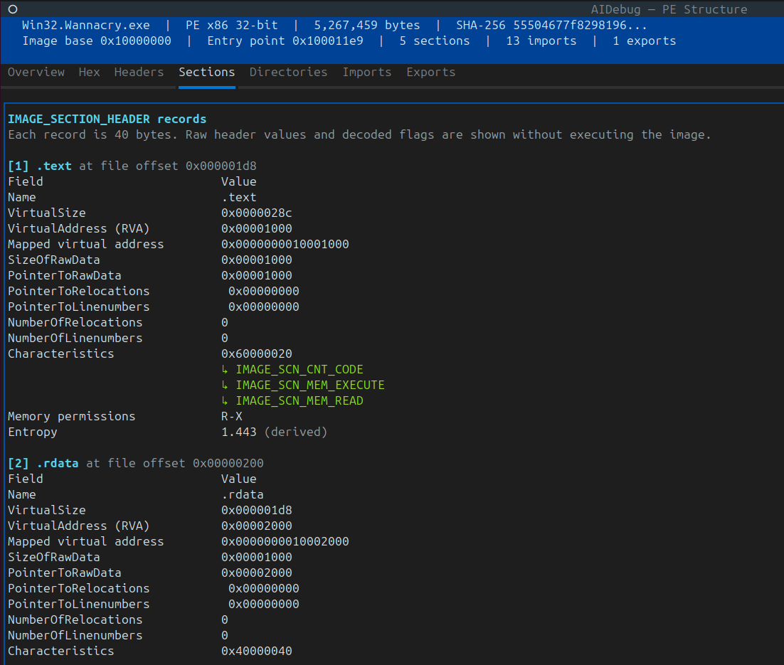
These are conventions, not enforcement. A section called .text can hold data; executable code can live in .data; packers routinely use custom or misleading names.
VirtualSize versus SizeOfRawData
The two sizes answer different questions:
SizeOfRawData: how many aligned bytes are stored in the file;VirtualSize: how much meaningful space the section requests in memory.
Common cases:
- Raw size greater than virtual size: the file contains alignment padding after meaningful virtual content.
- Virtual size greater than raw size: the loader zero-fills the remaining memory.
- Raw size zero, virtual size nonzero: uninitialized storage such as
.bss. - Both unexpectedly huge or inconsistent: corruption, unusual linker behavior, or evasion.
Do not hash or extract padding as if it were necessarily meaningful. Do not attempt to read zero-filled virtual bytes from beyond the end of the raw section.
Section characteristics
Content flags include:
IMAGE_SCN_CNT_CODE;IMAGE_SCN_CNT_INITIALIZED_DATA;IMAGE_SCN_CNT_UNINITIALIZED_DATA.
Memory flags include:
IMAGE_SCN_MEM_READ;IMAGE_SCN_MEM_WRITE;IMAGE_SCN_MEM_EXECUTE;IMAGE_SCN_MEM_SHARED;IMAGE_SCN_MEM_DISCARDABLE.
Useful observations:
- executable and writable (
RWX) is high-priority evidence but not proof of malware; - code in a non-executable section may indicate malformed metadata, a protector, or a parser mismatch;
- an executable section with high entropy and a small entry stub can suggest packing;
- a discardable relocation section is normal;
- a writable IAT-containing region can be normal because the loader must update it.
Section overlap and slack
Check for:
- overlapping raw ranges;
- overlapping virtual ranges;
- raw pointers inside the headers;
- sections extending beyond end-of-file;
- directory entries that cross section boundaries;
- data between the end of meaningful virtual content and the end of raw data;
- data between the end of one raw section and the next aligned section.
Slack can contain linker padding, stale bytes, deliberately hidden data, or nothing of interest. Its presence requires inspection, not immediate classification.
10. Imports, thunks, and the IAT
Imports describe external symbols the image expects the loader—or a delay-load helper—to resolve.
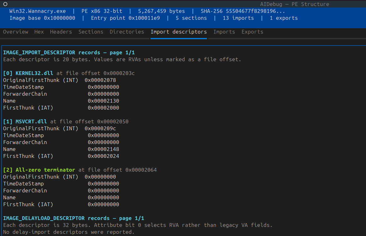
Import descriptors
The import directory is an array of IMAGE_IMPORT_DESCRIPTOR records, normally terminated by an all-zero descriptor.
Important fields include:
| Field | Role |
|---|---|
OriginalFirstThunk | RVA of the Import Lookup Table (ILT), also called the Import Name Table |
TimeDateStamp | Binding-related value |
ForwarderChain | Legacy binding information |
Name | RVA of the imported DLL name |
FirstThunk | RVA of the Import Address Table (IAT) |
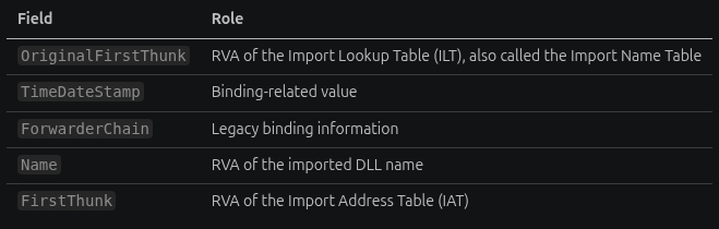
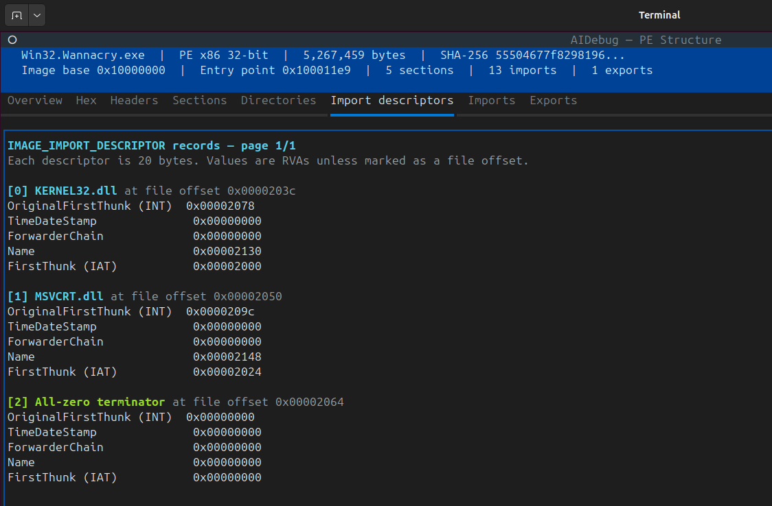
One descriptor represents one imported DLL.
Import Lookup Table
The ILT is an array of pointer-sized thunk entries:
- 32-bit entries in PE32;
- 64-bit entries in PE32+;
- zero terminates the array.
Each nonzero thunk usually identifies an import:
- if the high ordinal flag is set, the remaining bits encode an ordinal;
- otherwise, the value is an RVA to
IMAGE_IMPORT_BY_NAME, which contains a 2-byte hint followed by a null-terminated ASCII symbol name.
The hint is an optimization clue, not the identity by itself. The name or ordinal resolution is authoritative for the import request.
Import Address Table
On disk, the IAT commonly resembles the ILT. During loading, its entries are replaced with resolved function addresses. Calls can then use indirection:
call qword ptr [rip+__imp_CreateFileW]
An import thunk may end with a jmp through an IAT slot rather than a call. See the assembly guide for call-site and thunk interpretation.
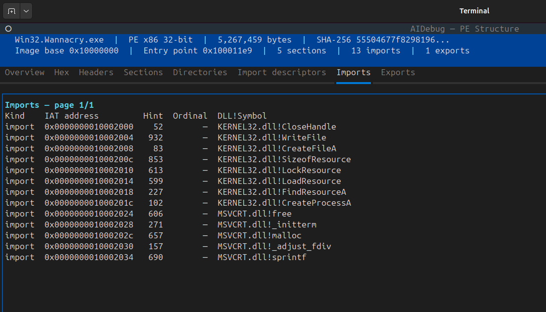
Imports as capability evidence
Imports help prioritize investigation:
| Import group | Possible question |
|---|---|
CreateFileW, ReadFile, WriteFile | What local or device data is accessed? |
RegOpenKeyExW, RegSetValueExW | Which registry paths and values are touched? |
OpenProcess, WriteProcessMemory | Which process is targeted and what bytes move? |
WinHttpSendRequest, connect, send | Which endpoint, protocol, and payload are used? |
CryptDecrypt, BCryptDecrypt | What data, key material, and algorithm are involved? |
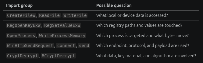
An import is not proof that a function executes. It may be unused, compiler-generated, defensive, or deliberately planted. Confirm cross-references and runtime paths.
For a deeper workflow, use PE Import Analyzer: A Practical Guide.
Missing or sparse imports
Very few imports can mean:
- a genuinely small program;
- static linking;
- managed code;
- runtime API resolution;
- a custom loader;
- packing or import reconstruction after unpacking.
Trace LoadLibrary*, GetProcAddress, export walking, API-name hashes, and indirect calls before concluding that a capability is absent.
Bound imports
Binding can precompute imported addresses for a particular DLL version. The loader validates binding information and may resolve normally when it is stale or incompatible. Bound metadata is a historical optimization and should not be mistaken for runtime proof.
Delay imports
The delay-import directory describes DLLs and symbols intended to be resolved on first use. A sample can therefore use an API that does not appear in the normal import directory.
Check both:
- normal imports at directory index 1;
- delay imports at directory index 13.
Malware reports that list only normal imports are incomplete.
11. Exports and forwarded functions
Exports make code or data available to other modules. They are especially important for:
- DLLs;
- plugins;
- service modules;
- reflective-loading investigations;
- samples launched through
rundll32; - drivers and native system components.
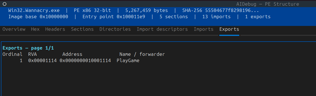
The export directory connects several tables:
- Export Address Table (EAT);
- Export Name Pointer Table;
- Export Ordinal Table;
- export-name strings.
Names and ordinals
Every EAT slot has an ordinal relationship, but not every export has a public name. The directory's Base biases public ordinal numbers:
EAT index = public ordinal - export Base
The 16-bit entries in the Export Ordinal Table are unbiased indexes into the EAT and run parallel to the Export Name Pointer Table.
Do not assume:
- ordinal 1 maps to EAT index 1;
- every EAT entry has a name;
- names appear in source-code order.
Forwarded exports
An EAT entry normally contains an RVA to code or data. If the RVA falls inside the export-directory range, it can instead point to a forwarder string such as:
KERNELBASE.CreateFileW
NTDLL.#123
A forwarder delegates resolution to another module and symbol. A disassembler that treats the forwarder string as executable code will produce nonsense.
Analyst questions
- Which exports have code cross-references?
- Which export is selected by the observed launcher?
- Are names descriptive, misleading, or absent?
- Does the DLL require a particular ordinal?
- Is an export a short forwarding thunk?
- Does the export table claim RVAs outside valid executable or data ranges?
12. Resources
The resource directory stores a hierarchy, conventionally:
Type
  └── Name or numeric ID
        └── Language
              └── IMAGE_RESOURCE_DATA_ENTRY
Common resource types include:
- icons and cursors;
- dialogs and menus;
- string tables;
- version information;
- manifests;
- HTML;
- arbitrary
RCDATA; - embedded executables, archives, configuration, or encrypted blobs.
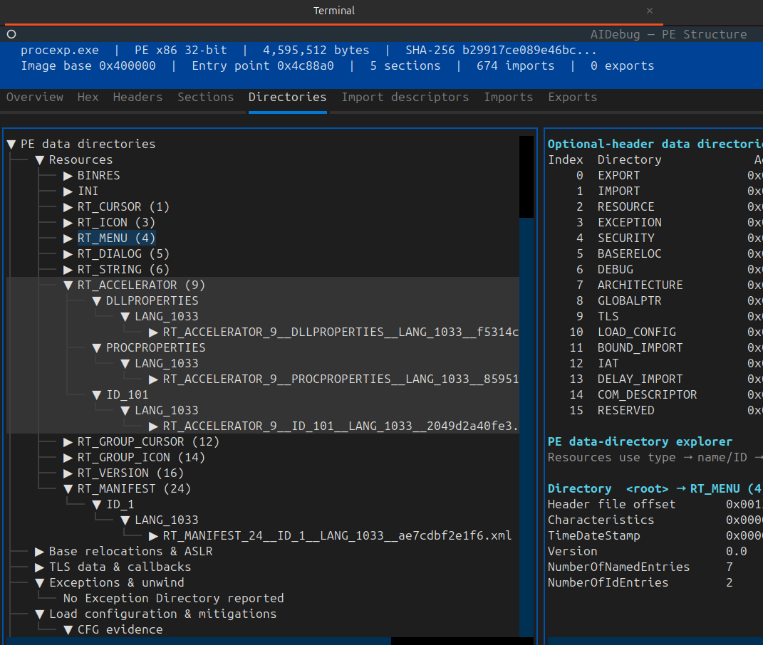
The final data entry contains an RVA, size, code-page field, and reserved field. Convert its RVA through the containing section before extracting bytes.
What resources can reveal
- claimed product and company names;
- requested execution level in a manifest;
- visual impersonation;
- language targeting;
- embedded configuration;
- decoy documents;
- secondary payloads;
- packer or installer content.
Version strings and icons are easy to copy. Treat them as sample claims, not publisher identity.
Safe extraction
Extract resources as bytes first. Hash them, identify their real format by magic bytes, and inspect them with the appropriate parser. Do not rely on the resource name or extension, and do not open an extracted child through the Windows shell.
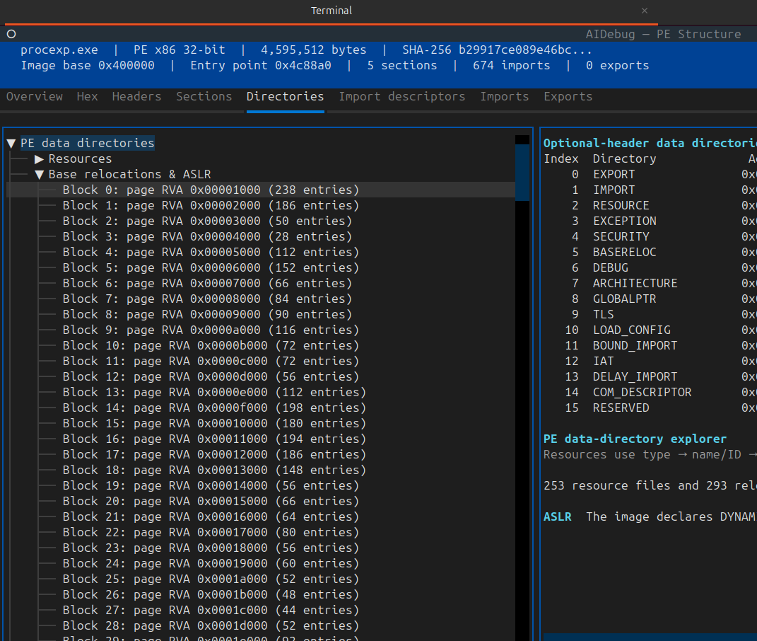
13. Base relocations and ASLR
ImageBase is a preference, not a guarantee. If Windows maps the image elsewhere, absolute addresses embedded in the image may require adjustment.
The relocation delta is:
delta = actual load base - preferred ImageBase
The base-relocation directory is organized into blocks. Each block covers a 4 KiB page and begins with:
VirtualAddress— page RVA;SizeOfBlock— total block size.
The remainder is an array of 16-bit entries:
high 4 bits = relocation type
low 12 bits = offset within the page
The target RVA is:
target RVA = block.VirtualAddress + entry.offset
Common types include:
| Type | Use |
|---|---|
IMAGE_REL_BASED_ABSOLUTE | Padding/no fixup |
IMAGE_REL_BASED_HIGHLOW | Add delta to a 32-bit field; common in PE32 |
IMAGE_REL_BASED_DIR64 | Add delta to a 64-bit field; common in PE32+ |
Analyst interpretation
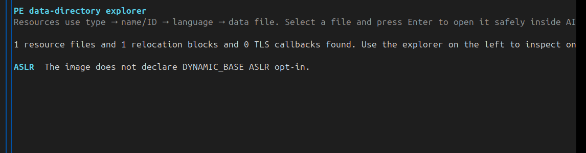
Practical ASLR normally requires both:
- an image that declares dynamic-base compatibility;
- usable relocation information.
If relocations are stripped, the image may need its preferred base. Drivers, fixed-base images, unusual loaders, and manually mapped images create special cases.
Relocation entries are also useful for distinguishing stored absolute pointers from ordinary integers during reverse engineering.
14. TLS data and callbacks
Thread Local Storage gives each thread its own instance of selected data. The PE TLS directory can describe:
- the TLS initialization template;
- an index used by the runtime;
- zero-fill requirements;
- a null-terminated callback array.
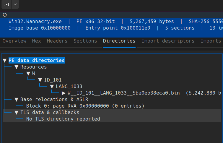
A crucial detail is that several TLS-directory fields are virtual addresses rather than RVAs. Parse them according to the PE32 or PE32+ structure and the specification.
TLS callbacks
TLS callbacks can run during:
- process attach;
- thread attach;
- thread detach;
- process detach.
At process startup, callbacks can execute before control reaches AddressOfEntryPoint.
Legitimate compilers use TLS callbacks for runtime initialization and object construction. Packers and malware may use them to:
- perform environment checks;
- decrypt state;
- initialize hooks;
- alter memory protections;
- terminate before the analyst's entry-point breakpoint;
- transfer control into an unpacking path.
Triage procedure
- Parse the TLS directory.
- Resolve the callback-array VA against the image base.
- Walk pointer-sized entries until the null terminator, with strict bounds.
- Validate that each callback points into a plausible mapped executable range.
- Disassemble and cross-reference every callback.
- In a debugger, set breakpoints on callbacks as well as the nominal entry point.
Do not label every TLS callback anti-debugging. Show what the callback does and how its result changes execution.
15. Exception and unwind information
Directory index 3 points to exception-handling data. Its structure is architecture-specific.
On x64, .pdata commonly contains sorted RUNTIME_FUNCTION records with:
- function begin RVA;
- function end RVA;
- unwind-information RVA.
The associated unwind metadata describes stack allocation, saved nonvolatile registers, frame usage, and exception-handling relationships.
Why it helps analysts
- recover function boundaries in stripped x64 binaries;
- distinguish code from embedded data;
- understand stack frames when a compiler omits
RBP; - improve disassembler and decompiler analysis;
- identify unusual handlers or missing metadata;
- support reliable stack walking during incident response.
Limits
- leaf functions may not need full unwind records;
- packers and hand-written assembly may omit or manipulate metadata;
- architecture formats differ;
- a table entry describes unwind mechanics, not business logic;
- corrupted ranges can confuse tools.
Cross-check exception records with control-flow reachability and actual section permissions.
16. Load configuration and exploit mitigations
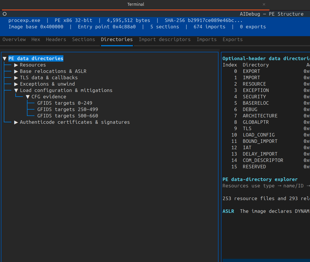
The load-configuration directory has evolved across Windows and toolchain versions. Its structure begins with a size field; parsers should use that size and the image's bitness rather than assuming the newest structure is fully present.
Depending on version and architecture, the directory can expose:
- the security-cookie address used by stack-protection logic;
- SafeSEH handler table and count for applicable 32-bit images;
- Control Flow Guard check and dispatch pointers;
- CFG function table and count;
- Guard flags;
- code-integrity metadata;
- dynamic-relocation and newer mitigation-related tables.
CFG evidence
For Control Flow Guard, correlate:
IMAGE_DLLCHARACTERISTICS_GUARD_CF;- load-config
GuardFlags; - guard function tables and counts;
- compiler-generated indirect-call checks in code.
A lone flag without coherent supporting metadata may be malformed, stripped, or misleading.
Security cookie
A security-cookie field can help locate compiler-inserted stack-protection state. Calls such as __security_init_cookie and failure handlers can reveal startup routines and protected functions, but they do not mean a vulnerability exists.
SafeSEH
SafeSEH metadata is relevant to compatible 32-bit images. It should not be projected onto x64, whose exception and unwind model differs.
General rule
Mitigation metadata describes build and loader expectations. It does not guarantee that every control is effective, that code is safe, or that the image was produced by a trustworthy party.
17. Authenticode certificates and signatures
Directory index 4 points to an attribute-certificate table, usually containing one or more WIN_CERTIFICATE records.
This directory is structurally unusual:
- its address is a file offset, not an RVA;
- its data is not mapped as an ordinary image section;
- entries are aligned to 8-byte boundaries;
- each entry's
dwLengthmust be rounded to the next 8-byte boundary when finding the following entry.
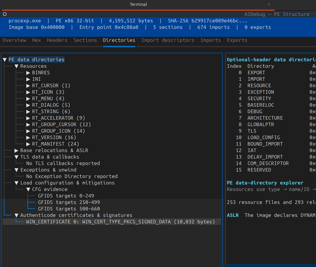
The image-digest calculation treats selected fields specially. In particular, the checksum, certificate-table directory entry, and certificate content cannot be hashed in the same ordinary way because adding a signature changes them.
What a valid signature establishes
Subject to certificate-chain, timestamp, policy, and revocation validation, a valid Authenticode signature can support:
- integrity of the covered file content;
- identity asserted by the signing certificate;
- signing-time evidence when a trusted timestamp is present.
It does not prove:
- the program is benign;
- the publisher's environment was never compromised;
- the certificate was not stolen or misused;
- behavior after loading is safe;
- unsigned overlay or externally retrieved content is trustworthy.
Analyst workflow
Record:
- signature presence;
- cryptographic validation result;
- signer subject and issuer;
- certificate thumbprint and serial;
- validity period;
- timestamp and timestamp authority;
- revocation result and whether it was actually checked;
- catalog signing versus embedded signing;
- warnings from multiple verification tools.
Do not report “signed” as “trusted.” Report the exact validation state.
18. Debug data, the Rich header, and overlays
Debug directory
The debug directory can point to several record types. CodeView records commonly begin with RSDS and contain:
- a PDB signature GUID;
- an age value;
- a path to the Program Database file.
A PDB path can reveal usernames, build directories, project names, branch names, or internal product terminology. It is useful provenance evidence but easy to remove or forge.
Some records expose both an RVA and a file pointer because debug data may be mapped or stored at the end of the file. Validate each location independently.
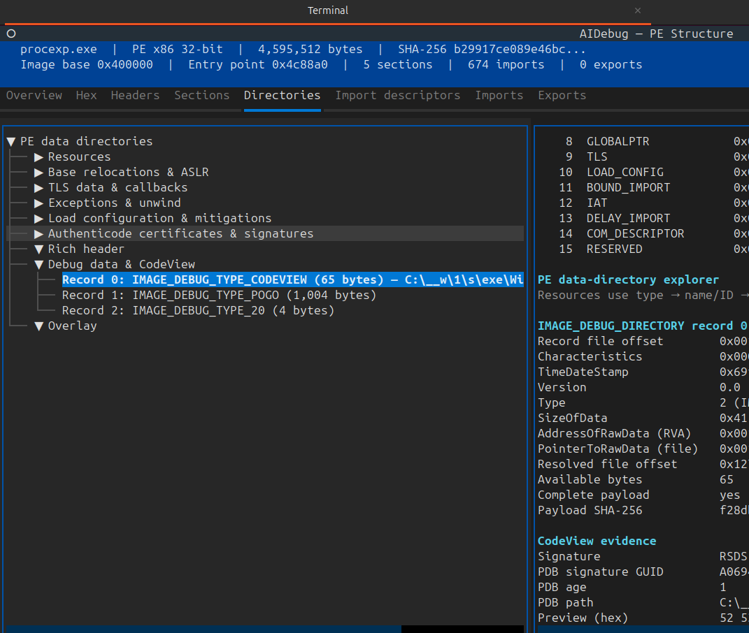
Reproducible-build metadata can make timestamp fields intentionally non-temporal. Do not force every 32-bit timestamp-like value into a wall-clock narrative.
Rich header
Microsoft-produced binaries often contain an undocumented, encoded “Rich” structure between the DOS stub and PE signature. Tools use it to infer product IDs, toolchain components, and build counts.
Analytical limits:
- it is not part of the documented PE/COFF contract;
- it may be absent from legitimate binaries;
- it can be copied, stripped, modified, or fabricated;
- product identifiers require an external interpretation database;
- a Rich hash is a clustering feature, not attribution proof.
Overlay
An overlay is data after the last expected raw image region. It may contain:
- installer payloads;
- self-extracting archive data;
- configuration;
- appended signatures;
- packer data;
- benign product metadata;
- hidden or encrypted content.
Be precise when calculating it. A certificate table commonly sits after section data and can look like overlay to a naive detector even though it is referenced by the security directory.
A defensible overlay report identifies:
- the end of the last valid raw section;
- any referenced certificate/debug ranges;
- the remaining unreferenced byte ranges;
- hashes, magic bytes, entropy, and extraction results for each range.
19. .NET assemblies inside PE files
A managed .NET assembly still uses the PE container. Directory index 14 points to the CLR runtime header, commonly represented by IMAGE_COR20_HEADER.
The CLR header can reference:
- metadata;
- managed resources;
- a strong-name signature;
- code-manager and fixup information;
- an entry-point token or native entry-point RVA;
- flags describing IL-only, 32-bit requirements/preferences, and related runtime behavior.
Metadata streams
The metadata root commonly contains streams such as:
| Stream | Content |
|---|---|
#~ or #- | Metadata tables |
#Strings | Identifier and name strings |
#US | User strings |
#GUID | GUID heap |
#Blob | Signatures and arbitrary blobs |
Managed types, methods, references, attributes, and IL are reconstructed from these metadata tables and heaps.
Analyst consequences
- a native disassembler may show only a small runtime bootstrap;
- the source-level entry method can be represented by a metadata token;
- imports may be sparse because framework behavior is described in metadata;
- IL decompilers such as ILSpy or dnSpy-derived tools are usually more informative;
- mixed-mode, ReadyToRun, NativeAOT, protectors, and embedded native code require both managed and native analysis.
Strong-name signing is not equivalent to Authenticode publisher validation. They serve different identity and integrity roles.
20. How the Windows loader uses the image
A simplified conceptual loading flow is:
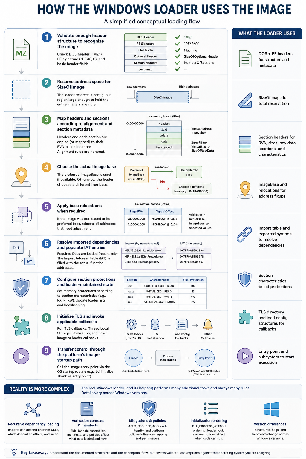
- validate enough header structure to recognize the image;
- reserve address space for
SizeOfImage; - map headers and sections according to alignment and section metadata;
- choose the actual image base;
- apply base relocations when required;
- resolve imported dependencies and populate IAT entries;
- configure section protections and loader-maintained state;
- initialize TLS and invoke applicable callbacks;
- transfer control through the platform's image-startup path.
The real loader is more complex. Dependency loading is recursive, activation contexts and manifests matter, mitigations influence mapping, DLL initialization has ordering constraints, and implementation details vary by Windows version.
Manual mapping differs
Reflective loaders, process hollowing components, packers, and custom in-memory loaders may reproduce only part of normal loader behavior. Analysts should compare:
- relocations applied or skipped;
- imports resolved manually;
- section permissions left overly broad;
- TLS callbacks invoked or omitted;
- exception tables registered or ignored;
- headers erased after mapping;
- memory layout versus the original
SizeOfImageand section RVAs.
This comparison can expose a manually mapped image even when its original PE header is no longer present in memory.
21. References
Primary and authoritative references:
- Microsoft PE format specification
- Microsoft IMAGE_DOS_HEADER structure
- Microsoft IMAGE_FILE_HEADER structure
- Microsoft IMAGE_OPTIONAL_HEADER32 structure
- Microsoft IMAGE_OPTIONAL_HEADER64 structure
- Microsoft IMAGE_SECTION_HEADER structure
- Microsoft ImageHlp image functions
- Microsoft Authenticode documentation
- Microsoft SignTool documentation
- ECMA-335 Common Language Infrastructure specification
- pefile project documentation
- LIEF PE format documentation
- AIDebug repository
- PE Import Analyzer repository